
|
|
#1 |
|
CGCars Member

Join Date: Sep 2005
Location: Barcelona
Posts: 143
|
Featured: Brake caliper Tutorial by NeoLitus
This is the first part with the entire block modelled, and the second part will come later with the little details that are missing here :P
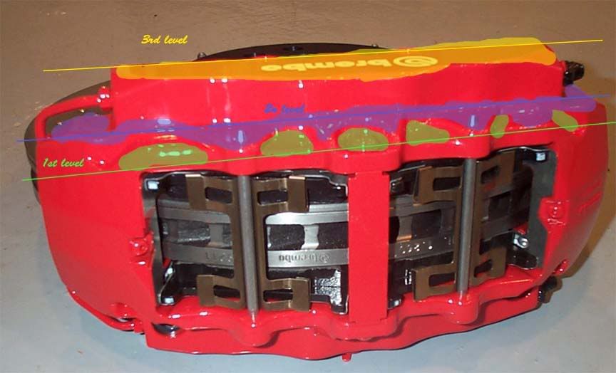
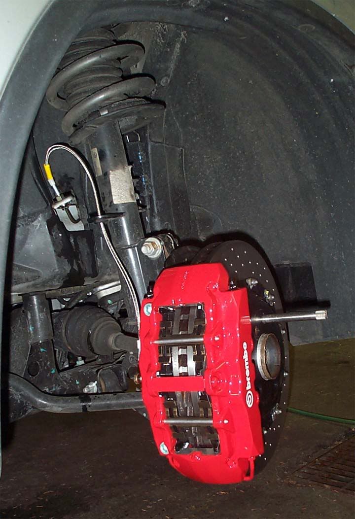
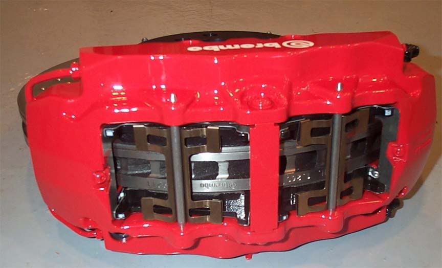
First of all you need to search a lot of reference and use one like a base, put brembo calipo in google images and they will find a lot of pictures, but well, you can use this like a reference for modelling. And well, I made a brembo because it’s one of the most common ones in the top performance cars, but you can try with the brake that you want. I’ll use a box modelling because I feel more comfortable using box modelling than splines or nurbs, but may be with splines could be more quick. Then lets begin, put a box with 4x4x1 segments(we will extrude the height later), use edit poly and start to move the vertices: P (Remember that we only gonna make a half part for now). Really, it’s better made a box with 4x4x2 and erase the last segment, with this form we will erase the bottom face at the same time and we won’t need to select all the polygons an erase them manually :P  Well begin to start cutting we need to see that for the base we will need to made 3 levels.  You’ll be realize soon that we can’t make all the calipo with only 4 segments, then, use the QuickSlice for create more edges and vertex in the box. If you want a lot of definition then cut in a lot of points and if you don’t search the perfection (remain that this is a “secondary” part of the car) you can make less cuts for improve the time of the render. Well, like we are a fucking freaks :P and we search the perfection I will try to make something nice.   Like you see in the photo, I use the original mesh and I cut in a lot of points, the green zones are made with the extrude tool, extruding the side polygon an erasing the bottom one. Then like you can see, I put the lines following the reference of the 2nd level (remember that we have only 3 levels on this photo)  Now before extrude, we will make all the cuts that we need for the 2nd and for the 3rd level. The cuts are mark in yellow.  Like we don’t have a real reference about the size of every level and of the real brake (well, I can’t find one) we will made using the reference of some photos (yep, I know that this is not the right way to make the things but we don’t have nothing more). Then select all the polys that need to be extrude for the 2nd &3rd level and extrude them one time… Deselect the ones that need to remain in the 2nd level and leave selected only the ones that need to be extruded one more time and extrude them until you think that it’s a good high mmmmm…I see now that I made a mistake in the mesh T_T, but well, like all the problems we can solve this easy, select the polys of the first side level that we forgotten to put in the right place(well, I realize of that when I see another photo in the side, because in the first reference photo it seems that the photo have a little angle).   Well, extrude the polys, erase the ones of the bottom and the ones of the left and right side respectively and weld the vertex.  We start to finish this, then move this to vertex down.  We’ll start the other part of the mesh, and for this, we need a reference, we can load some disc that we have made, make one here with the reference photo for the caliper or we can make with some reference photos and trying like the height xD.  We’ll select all the edges that we need to extend, and move down 2 times with the shift pushed.  We need to adjust the middle part.  Well, the mesh is “finished”, we need to put a meshsmooth and make the chamfer tweak in the border lines for control the meshsmooth. For ones that don’t know, the tweak consist in select all the lines that are in a border and put a very small chamfer, then when we active the meshsmooth the border will be a border and not a curve. In really, we can use a normal smooth (the one with numbers) with a very very nice result, because basically the borders are in angles of 90º but we have money, we have pc’s and we want a high poly caliper, no¿?(sorry for my freakness xD) Will be better if we put the chamfer only in the 3 levels for now, not in the part that we made later, well, the one that goes down on the side because we need to make a symmetry and weld, and will be better to put the chamfer after that we will make this.  Then, I think that the caliper looks good now, make a symmetry (copy, remember to delete the meshsmooth first) in the z axis and then attach one side with the other and weld the vertex of the middle.  May be when you’ll attach, the mesh rotate the normals (I don’t know why), but we can select the polys and flip them manually with the option (this is one of the reason for what is better work with edit poly and not with edit mesh).  Weld all vertex.  Make a chamfer on the edges of the middle part and add the meshsmooth with 2 iterations. Now we have the entire block and we only need to make the little details like screws, the name… 2nd part: If we take a look to the reference photos that I post 3 replies more down form here, we can look that the front part and the rear one are different only for two holes and two “screws” all the other in theory it’s the same. In this part you can follow the order that you want, because it’s the same make the screw first than make the brembo logo. Now, we are going to make the screw of the middle in the front part. Like I hate the splines, I will make this with poly modelling but this is easiest in splines than poly. Well, create a cylinder with 1 and 5 segments and the 16 sides(for make more easy the star cut).     I don’t put text because these things are more simply to explain with photos than talking. For the brembo logo we only need to adapt the two plans with an uvwmap and put a map like this on the mask. If somebody doesn’t know how to make this, say something.    I don’t know how really these two “screws” are; then, I will make something easy like the photos xD.  Well, a simple cylinder 3x1, moving the middle edges to the top and bottom, making a chamfer and extruding later, and the scale tool used for the high top and low bottom side for resize. Now, it’s the time for use splines xD but I was trying and I’m very tired for search how to do, but with a line, circle and hexagon you could make the same in less time with loft tool, but I don’t know why I put all good and the fucking program make what he wants xD, then I will use the poly modeled like always xD  Basically, take a cylinder with some edges, move and rotate until the half part, then add the hexagon (this can be made quickly with splines, circle+hexagon, convert to edit poly and shell for the volume), take all and make a mirror, attach and weld, like the other times, you know  A simple object made with two cylinders and the hexagon that I made before. Well, I think that all is finish, i dont make the two screws more of the rear part because i need to sleep a little now and update for only 2 screws that are a simple hexagon with an emptiness interior... I hope that this could be useful for someone and sorry for my English, if you can’t understand something don’t hesitate and feel free to comment. Last edited by NeoLitus; 27-12-05 at 08:28 PM. |

|
|
|
#2 |
|
Junior Member

Join Date: Nov 2005
Location: Lithuania
Posts: 43
|
AWESOME TUTORIAL
but if u can make a tut by the disc |

|
|
|
#3 |
|
CGCars Member
 |
Well Done,
Thanks for taking the time to create that. It takes a lot of time to actually sit down and construct a tutorial.  One little comment ... as the Caliper is actually symmetrical about its centre you could focus on modelling just one half and use symmetry on it ? Dave
__________________
DMMultimedia HomePage Old School Fords, Max/MR and Schnorbill Texturing/Rendering Tutorials |

|
|
|
#5 |
|
CGCars Member

Join Date: Sep 2005
Location: Barcelona
Posts: 143
|
May be i'm wrong, but in theory it's symmetrical, well all the photos that i could obtain from the net it looks symmetrical, but in the rear part have two holes more, but the block it's the same.
   and for the rotor i made the same as the tutorial that equinox put, but I put a shell for made more width, the mesh duplicated, and rectangle blocks in the middle of the 2 sides. |

|
|
|
#9 | |
|
Junior Member

Join Date: Dec 2005
Posts: 8
|
Quote:
 |
|

|

|
| Bookmarks |
|
 |
The thread "Featured: Brake caliper Tutorial by NeoLitus" has not received any replies for 4 months. It has been automatically closed as a result. If you are the Thread Starter or the Thread is a Collective Thread and you want to post a reply, please contact an Admin or a Moderator via pm to reopen it. |
| Currently Active Users Viewing This Thread: 1 (0 members and 1 guests) | |
| Thread Tools | |
| Display Modes | |
|
|
|
|||||||||||||||||